In the heating system without pump, piping and valves, but these are also the noise sources. Said the first pipeline, liquid flows through the pipeline, the pressure and friction of turbulent excitation disturbance will produce noise, especially when the turbulent Reynolds number Re>2400, turbulence that contain tiny vortex large irregular, can be said to itself in a "noisy" state. In particular, flowing through the throttle valve or pipe pressure, abrupt change of cross-section or abrupt bend of the elbow, turbulence and these obstacles to fluid through the part of the interaction of the vortex noise, the sound power level (dB) with the change of flow rate can be expressed as: Lw=60lg, if the pipeline design is not when also can produce cavitation noise; and the valve with the throttle, or pressure limiting valve of noise source, is the largest liquid transport pipeline. When sufficient fluid flow within the pipe, if part of the valve is closed, the formation of a large area in the choke valve, in the choke area of liquid flow rate increased and the internal pressure is reduced, when the critical speed is equal to or greater than the medium flow rate, pressure of less than or equal to the evaporation of the medium pressure, the formation of bubbles in the fluid. Bubbles with the liquid flow, downstream of the choke valve velocity decreases gradually, static pressure, air bubbles have been broken, causing the fluid pressure in the irregular fluctuations, the turbulence of this particular phenomenon called cavitation, which called cavitation noise generated by noise. In the large pipeline flow, high pressure, almost all of the throttle gate will produce cavitation noise, the cavitation noise down the river can spread very far along the pipeline, the random noise can stimulate the valve or natural vibration of moving parts in the pipeline, and the role of these components spread to other parts of the adjacent pipe surface, produce similar metal collision sound produced by a tone. The seven party acoustic cavitation noise power and velocity or proportional to eight, so as to reduce valve noise, multi-level series valves can be used, the purpose is to progressively reduce the flow rate. As we often use the valve, using the low prices of the flow, so when the fluid flows through the valve chamber, the valve will be below the control (namely the choke area) to form a low pressure high speed region, bubbles. High-pressure valve and then through the low velocity zone, bubbles have been squeezed broken cavitation noise.
Based on the above analysis shows that the channel noise, valve noise are related to the liquid flow state, in other words, with the pressure and flow rate.
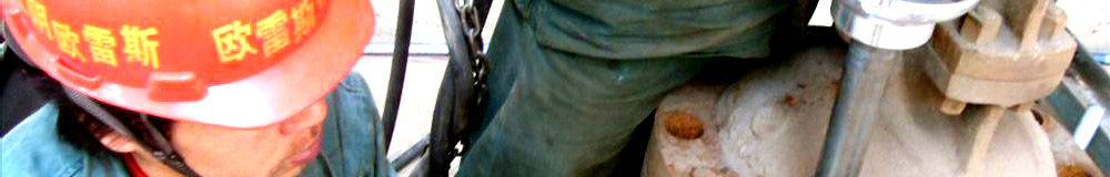
Self-operated flow control valve noise survey of velocity, pressure generated by the
Here is our field survey data. Tianjin factory floor Chaoyang District Heating, heating area of 265000 square meters, the pipeline laying method: outdoor overhead, the heat transfer station in four loop for. Southern diameter DN250 for area 132000 square meters, diameter DN250; the area of 108000 square meters; the spring diameter is DN200, the area of 12000 square meters; 34 floor diameter is DN150, the area of 8012 square meters. Tenants reflect the 34 floor and the spring installation of control valve noise. In March 3, 2003 we conducted on site test (equipment, ultrasonic flow meter, noise meter), data are as follows:
The measured indoor noise 34 floor, 2, 3 units of 57 dB; the spring breeze of No. 1 Building 1, unit 3, 58 dB ~ 60 dB, while the Southern District 1 floor 1, 3, 5 units of 45 to 47 dB. From the above data, although each household unit flow rate did not exceed the design requirements, but due to the relative monomer flow rate too fast, a larger pressure difference, resulting in cavitation noise in the control valve. 34 floor of the differential pressure is 0.06Mpa, and the Southern District 1 floor pressure is 0.02 Mpa, the formation of another cause of local flow speed and pressure are 34 floor and the spring from the heat exchange station is close. The remote user entrance distance of 350 meters, while the South's most remote 1000 meters, is a system with significant differences between the distance, households resulting pressure difference between the large velocity difference is also large. As the pipeline is installed overhead cavitation noise and the frame of this resonance makes another pass to the interior noise, this situation also occurred in the dawn of the Liaohe oil field operation area. Not only is the overhead lines, underground pipelines can also produce cavitation and turbulence friction noise. As a district heating pipeline is buried in Beichen District, tianjin. After the installation of flow control valve noise increased significantly, measured up to 65 dB. Ask the user that there before, but not now large, the control valve is removed, the interior was also measured up to 58 dB, the reason is due to heat balance is not good, individual monomer pressure, flow velocity is too fast. The seven party said that acoustic cavitation noise power and velocity or eight time is proportional to the square of velocity, therefore, although only a little, but the noise has increased greatly. In view of the above situation, the Chaoyang floor area 34 floor we have taken a step by step buck or gradually reducing the available pressure head and flow rate. The main branch of the outlet valve (DN150) is adjusted, and the valves adjusted unit households. Retest 34 floor entrance pressure difference control in the 0.03 ~ 0.05Mpa, and then measured indoor noise 2 unit 102 has been reduced to 35 dB, 3 units of 101 to 40 dB, has been to meet the needs of.
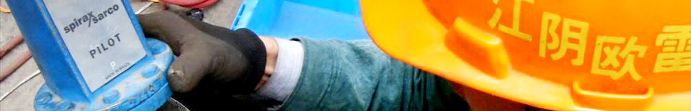
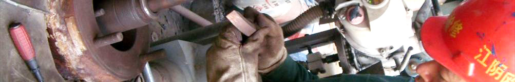
Self-operated flow control valve noise generated.
As already mentioned the relationship between the sound power level with the velocity change △ Lw=60lg, △ P=KVS, by G2 and V= can be obtained, so that when the flow coefficient (KVS), flow area (R2) is given, the sound power level can also be expressed as Lw=60lg, while the self-operated flow control valve is adjust the pressure to achieve the purpose of flow control based on. So how to ensure that the pressure and to achieve the purpose of noise reduction, according to the measured data and theoretical analysis above, we use the multi-stage step-down structure. The manual valve changes shaped oblique cocks, making the performance to ensure the circulation flow rate can be reduced, this is the first level; secondly, the automatic valve is changed into a double arc, double valve structure, fluid flow through the first circular surface on the valve, and then through the lower arc surface that is easy to reduce the flow of fluid through also, this is the second stage; then flow through the valve on the circular surface and a circular surface which is the third level. At the same time in the automatic valve with a side of the ribs to the diversion, but also can eliminate the formation of air bubbles in the fluid. In order to eliminate the low pressure generated by high-speed zone choke, we started in the control valve and manual control at the entrance to increase the damping to reduce network flow, reduce choke, but after testing is not feasible, because the damping network although the corrosion resistance (made of stainless steel), but the diameter of the mesh can easily cause congestion constraints; we will automatically change the comb-shaped valve, the purpose is to reduce the formation of bubbles high-speed zone. But because of the shape and intensity of the comb is not conducive to long-term use, and therefore not used. Finally adopted a multi-stage noise reduction structure. We tested nearly 1000 times of continuous improvement, the control valve noise from the original 65 ~ 75dB down to the current 45 ~ 55 dB.
These two transformation makes the self-operated flow control valve in the use of scope has been further expanded. Our noise reduction valve has batch production, and more than a dozen customers orders. Life of a patented product is generally 30 to 50 years. Self-operated flow control valve has been available for ten years in our country, has gradually become the generic products. How to let users better understand the use of heating of the product is the direction we continue to work, we will also continue efforts, development of new products for the heat users.
The article explains:
1, this is the network editor reproduced or the release, the release of the article aims to convey more information to visitors.
2, involves the content of the works, copyright and other issues, please contact with the network in 30 days, we will make the appropriate treatment for the first time! The relevant copyright matters please contact: 13515194999
3, this article please indicate are from: Jiangyin OuLeiShi valve valve repair factory www.olschina.com
4 other links:
Valve repair valve repair valve repair equipment valve grinding machine import valve repair valve repair valve repair
|