Composition of gas pipe, oil pipe and water pipe, pipeline network, often have to install the valve device for emergency cut-off in the key position, to prevent the leakage of pipeline accidents within the case material. The earliest use of cut-off valve is a mechanical type structure, each valve shutoff and open to staff on-site manual operation, the process is complex, and because the commuting time consuming, not conducive to the timely processing of emergency. With the development of pneumatic technology in industrial application, the pneumatic cut-off valve, in each body next to the placement of a tank, is controlled by the electromagnetic relay gas channel to realize the valve, pneumatic valve and mechanical valve also increase the remote control function, the operator through the computer remote control of central control room. Gas tank theoretical case for the valve work for 1-3 years, but in fact, the machining accuracy of gas, only 3 months was leaked. Therefore need to design for outdoor environment, with a cut-off valve remote control system of central control.
Functional overview
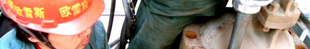
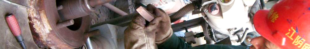
Cut-off valve installation position in the wilderness, bad environment, each part of the system design must consider the specific use of the site. In the power aspect, cannot be used by industrial power, the design of the system, using the solar power; in the choice of components of the power to adopt a low voltage, high efficiency, low cost, easy maintenance of the brushless DC motor; remote control by using the 485 communication protocol of industrial standard, so easy and pipeline flowmeter, pressure meter and other equipment is compatible with digital control system. The structure of control system frame.
The system used TI 's LM3S615 as the main control chip, BLDC control with position sensor three-phase, the whole system adopts closed-loop control, adjusting the speed and current, between the cascade connection, also is the output speed regulator as a current regulator input, control output trigger power switch tube and the current regulation device.
The hardware design mainly function unit
Part of the design of the main circuit
The main circuit part of motor steering control and speed, this part includes the power drive and full bridge inverter. Inverter adopts winding utilization of three-phase H bridge circuit with high, smaller torque ripple component. Power switching tube is the core component of the main circuit, taking into account the working voltage, current and power factor, IRFI3205 inverter bridge circuit used in this system, which is a full control type MOSFET tube, as its main parameters, VDSS=55V, RDS ( ON ) =8m Ω, ID=56A left margin. The main loop circuit diagram is shown in figure 2.
Figure C46, C47, C48 is the bootstrap capacitor, value of 10uF, D8, D9, D10 is the bootstrap diode, often using ultrafast recovery diode, taking into account the reverse voltage is not high the Schottky diode ( 1N5819 ), RS is the current sampling resistance, because the chip internal current comparator using 0.5V reference voltage, maximum current 15A design of the system, obtained RS 0.033 euro /10W. R51, C45 RC low pass filter, to prevent interference pulse error action. Rs, Cs, Ds buffer circuit. R57- R62 is on the MOS gate electrode capacitor discharge.
Current detection and protection circuit
Current detection methods including the common current transformer, Holzer current sensor and resistance sampling method. The current detection circuit is used in the system is shown in figure 3. Through a series of precision sampling resistance RS is connected to the DC bus will be the main loop current signal into voltage signal, low-pass filter, the voltage signal through the R51, C45 were divided into two, all the way to IR2130 ITRIP end, with current hardware protection; another way into analog voltage is composed of LM324 the amplifying circuit conditioning 0-3V range, the voltage signal by the zener diode D6 limiting to the LM3S8962 analog / digital conversion channel ADC0.
Voltage detection and protection circuit
This design is used in the detection of voltage divider resistors, precision and precision potentiometer divider sampling circuit, the voltage low pass filter, then through a voltage follower to ADC port. In the main program by polling the read voltage value judgment of DC bus voltage is normal, once the abnormal situation, close the PWM output.
Position and speed detection circuit
Not with three Holzer position sensor inside the brush DC motor, the motor in the rotation, through the judgment of three position logic, make the phase change, right at the same time, through the computation between two commutation pulse time difference, but also indirectly derived from the motor rotation speed, provide data for speed loop control. The Holzer element is open-collector output, the output signal through a pull-up resistor to get position square wave signal. Considering that does not match the Holzer output signal level and the main control chip level, Holzer output position signal after isolation circuit is composed of optical components, through the low pass filter is composed of RC and two Schmidt gate after shaping into chip.
Communication module and address position detection module
With the 232 module piece of MAX485 and LM3S615, completed the data communication between the host computer and. Address code by a 8 dial switch, photoelectric isolator two position detection is installed in the valve, the valve for the judgment.
Software design
According to the function division of system implementation, software design is divided into: main program, interrupt subroutine, position detection of voltage / current detecting interrupt subprogram, timer interrupt program and communication program. Because of the limited space, here only introduce a part.
The main program
To realize the system initialization program, open the system global interrupt, called motor pre-start program and main program loop body. Initialization includes header file to load, variable configuration and communication module, clock module configuration, the definition of ADC configuration module, timer module configuration, the PWM module configuration. The motor on the electric moment in a static state, no position signal for commutation of judgment, and therefore must be pre start to rotate the motor. Every time, then detect the motor state and the corresponding control.
Position detecting interrupt subroutine
The interrupt signal to this part of the program detects a position, a decision the next time the commutation logic, on the other hand, the calculation of the current speed. Motor system is a large inertia system, especially the speed loop hysteresis phenomenon is quite serious, if the speed adjustment is too frequent cause system oscillation, therefore in the software and timer mode of matching, a fixed time every, value for an average of multiple computing speed, then taking the average value as the speed measurements adjust control corresponding to the motor.
Communication subroutine
Chip baud rate 9600, 8 data bits, 1 start bit, 1 stop bit serial communication mode, data is transmitted in frames format, frame format is divided into two kinds: a kind of frame is used to transmit commands or state, composed of six bytes, another frame for transmitting data, consisting of by the 7 bytes.
Taking LM3S615 as the cut-off valve control system, with perfect function, high control precision, after experiments, long-term stable and reliable, competent in the field of demand.
The article explains:
1, this is the network editor reproduced or the release, the release of the article aims to convey more information to visitors.
2, involves the content of the works, copyright and other issues, please contact with the network in 30 days, we will make the appropriate treatment for the first time! The relevant copyright matters please contact: 13515194999
3, this article please indicate are from: Jiangyin OuLeiShi valve valve repair factory www.olschina.com
4 other links:
Valve repair valve repair valve repair equipment valve grinding machine import valve repair valve repair valve repair
|