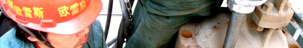
Heze longbeng Vehicle Co. Ltd is specialized in the production of petroleum machinery manufacturers, production of plate valve for years, as shown in figure 1. Flat valve production, structure is very simple, is the most common oil. Sealing principle is also a familiar, a wave spring is mounted in the valve body by the driving seat on both sides of the valve plate respectively, so that the seal face always attached to the valve plate sealing surface, so as to realize a seal, as shown in figure 2. And the valve plate can move freely between the two seat, so as to realize the opening and closing of the function in figure 3. In the design of the flat valve, in accordance with the analogy method in the past, as long as the basis of the old product ratio of the main parts amplification can be. This is a very fast design method. In a preliminary trial of PFF7870 is simply using this method. To shorten the manufacturing cycle, but the result has proved that this is not a reliable strategy. Due to the tail of the valve seat stress section is too small, the local stress in the dangerous section, as shown in figure 4A the trial flat valve seat, valve plate suffer from the pressure, resulting in the tail of the valve seat caused by the local stress and deformation expansion into a horn shape, resulting in the valve seat and valve stuck with Kong Guoying, the waveform of the return spring failure, causing the valve plate and valve seat sealing surface between the cannot be attached to produce the gap, makes the final seal failure, type test failed.
To find the causes of seal failure, more aware of the importance of comprehensive stress analysis of mechanical parts. But only by the traditional calculation method of irregular shape parts of analysis and calculation is very difficult to do everything. If the valve stress checking calculation is just put the body structure is simplified by a complex of four structures for a through the thick cylinder, failed to complex characteristics of the structure itself is fully considered, resulting in model and actual stress deviation, bring greater error to design calculation. I have to solidWorks and CosMos for finite element analysis platform, which makes the design and verification becomes fast, comprehensive, and reliable. The following is by comparing the two design of the three-dimensional modeling software solidWorks and finite element analysis software CosMos combination, process valves of the three-dimensional design and finite element analysis.
Analysis of the stress state of the valve seat
As shown in Figure 2, closed in the flat valve state, from upstream closed fluid pressure is divided into two parts in the valve plate. A portion of the force is a direct role in the valve plate, if the set: D -- D -- seat seat diameter; diameter; P -- rated working pressure plate valve; this part is: F1 = /4.d2.P. The end face on the upstream of the valve seat on the other part of the force: F2 = /4. ( .P D2d2 ). Due to the upper reaches of the inner end face against the seat in the valve plate, so F2 has been transmitted to the upstream seat of the valve plate closed, such stress conditions the valve plate is F = F1+F2. The valve plate and the force F is transferred to the downstream seat. So in the end the downstream seat stress for the F = F1+F2 =π /4.d2.P.
DolidWorks to establish three-dimensional solid model
Using the function of modeling solidWorks powerful seat according to figure 4, the B a section are respectively established entity model:
The preliminary model.
C optimization model.
Special attention should be paid to unit of the modeling process, should ensure that used in SolidWorks in CosMos unit. But sometimes there is a need for direct input some derived quantities ( such as force, pressure and so on ), then you must ensure that these quantities are derived and the basic physical quantity which belongs to the same system of units, or need to dimensional conversion. So in the solidWorks of every parts of the unit the best setting for the international system of units " MKS " ( MeterKilogramSecond ).
The seat of the three-dimensional entity model is divided into the following 2 process based on solidWorks:
The 2D sketch plane.
Rotating sketch generation entity.
Finite element analysis of the seat.
Into the seat model
Because the seat structure around the symmetrical structure, based on the simplified model theory, the seat is divided into 1/2. Through a seamless interface CosMos and solidWorks software, will seat model is imported into CosMos software, so as to realize the interchange between the two data, a truly integrated CAd, CAE.
Set the element type and mesh
Grid is a very important aspect of modeling, choosing the mesh form is an important factor to determine the accuracy of grid quality and results. If you use a sufficiently small unit size, based on different preferences set results should be mutual convergence. According to the structural characteristics, the seat of the load type and of the need for physical grid, mesh type. The minimum mesh size of the wall should not be greater than the seat of the thickness value. Finally the method of grid division of free mesh, the mesh model of the setting information, see table 1. Grid model as shown in figure 5.
Setting material properties
According to the classification of APisPEC6A " wellhead and Christmas tree equipment specification ", the seat of the pressure control, Psl2 level for above products should adopt high quality forgings. Open the CosMos editor ProPErtYMANAGEr, performance parameters of the material, see table 2.
The constraint and load
According to the seat of the stress state of the first trial, seat and seat after the optimization design model was applied to the following conditions:
( 1 ) add symmetry constraint: applying symmetry constraint on the model in the symmetrical section.
( 2 ) add fixed constraints: in order to make the simulation and actual situation closer, to seal valve seat ( surface and the valve plate. " ) given constraint type fixed" ( namely the limit all the translational and rotational degrees of freedom ), as shown in figure 6.
( 3 ) applied surface load: load characteristics as the uniform distribution, according to the test pressure and given in the seat of the seating stress formula, the tail end seat are respectively applied load: seat first trial production force F = 606132N; optimization design of seat after force F = 665234N, as shown in figure 7.
As close to the tail end position in the danger zone of the valve seat ( Figure 4a), the accurate analysis of this definition the constraint and load can obtain the dangerous area value.
Solution
Select the FFEPlus solver, automatic computation by computer.
The results of finite element analysis results
Finite element analysis of post processing and display the results, the main purpose is to check the results after the treatment, the structure static analysis of this case belongs to, so choose the universal post processor for the results of inspection. The results in Figure 8 to 9.
From figure 8 and Figure 9 presents the results of root causes of seal failure, can find the initial trial products, due to the initial trial seating stress section is too small, causing the local stress is too large and the valve seat tail expansion into a horn shape, and surplus card dead and the valve body, the valve return spring failure, thus resulting in seal failure. Another point should be noted, the valve seat sealing groove position is not appropriate, the seal groove is too close to the tail is one of the causes of the dangerous section stress seat formation. It is because the results from the finite element analysis to find the root of the problem, in order to carry out the optimization direction of optimization design, structural form of seat design is determined, as shown in Figure 4B. It can be seen that the optimal scheme adopted two measures: first, the seal groove is far away from the tail end, second, increase seat diameter size of D. The two measures taken for the purpose of increasing the risk of cross section area, reduce the stress value. Through further analysis, as shown in Figure 8b and figure 9b, indicates that these measures are very effective. As the final products of the successful trial provides guarantee.
Through the above examples show the use of 3D modeling software solidWorks and finite element analysis software CosMos seamless connection, can successfully stress state on the seat of the precise analysis. This method can greatly simplify the design process of product, shorten development cycle, improve production efficiency and the reliability of the design and integrity, has very important significance to promote the development of special valve oil field.
See from figure 8b " optimization design of seat after stress nephogram " can be: SE = 510MPA SY = 517MPA ( where SE is " in accordance with the deformation energy theory method for the calculation of the pressure vessel wall at the position of maximum compression maximum equivalent stress; " SY " material specified minimum degree of Qu Fuqiang " ) the relationship between APisPEC6A, meet the " wellhead and Christmas tree equipment specification " of section 4.3.3.3 requirements.
The article explains:
1, this is the network editor reproduced or the release, the release of the article aims to convey more information to visitors.
2, involves the content of the works, copyright and other issues, please contact with the network in 30 days, we will make the appropriate treatment for the first time! The relevant copyright matters please contact: 13515194999
3, this article please indicate are from: Jiangyin OuLeiShi valve valve repair factory www.olschina.com
4 other links:
Valve repair valve repair valve repair equipment valve grinding machine import valve repair valve repair valve repair
|